06F 129 101 G New breather ('PCV') valve
06F 103 215 A New pipe with checkvalve
06F 103 483 E Gasket
06F 145 757 F Gasket
The part numbers listed above are the recommended solution.
When I install those parts, I'll post an article with instructions.
Before these new parts were available, another means was devised to supplement the stock brather valve, and either protect for a non-failed valve or compensate for a failed one. The solution was originally posted by 'digitalhippie' on the VWVortex 2.0T FSI forum. He located a check valve that was heat- and solvent-resistant, and which had opening and holding pressures that would work perfectly for this application. Putting this checkvalve in the breather line would prevent backpressure from reaching the original breather valve and leaking past it. I provided him with photos of how he originally described implementing the fix, but at the same time I posted that I would probably improve upon the idea by using silicone hoses.
The thing with finding silicone hoses is that the fittings on the engine work best with 19mm ID hose, and the new checkvalve fits tightly in 16mm ID hose. I located 19mm --> 16mm reducing elbow hoses and tried them as part of a new checkvalve assembly. The valve will screw tightly into the 16mm ends of the elbows (trimming of excess hose length is necessary), and I have so far not found the need to clamp the hose at the valve since it fits so tightly. The seal is such that no thread blow-by can occur.
I discussed this idea with the hose vendor, and they were cautious about using non-flurolined hoses because of possible degradation due to oil exposure. Given this, I'm going to keep an eye on the hoses to see what the long-term effects are, but I'm not overly concerned because the amount of oil exposure is relatively small.
Note: Several people who have tried this solution have reported failure of the checkvalve. This could be due to damage from applying too much clamping force on the valve instead of using tightly fitting hoses like I did, but there is no definitive answer as to what caused the valve failures. This article is provided for information only, do this at your own risk.
Installation of the McMaster valve:

This is the valve. It is available ONLY from McMaster-Carr. The part number is: 1424T37 (Nylon Spring-Loaded Piston Check Valve 1/2" NPT Male Inlet X 1/2" NPT Male Outlet).

This is the stock pipe that we will replace. Note the direction of flow! When you install your new valve & hose assembly, make sure to verify that the valve flows in the correct direction!
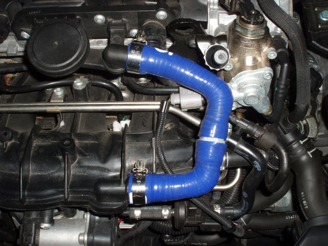
This is the new hose and valve assembly. The hoses must be trimmed slightly on each end. The silicone reducing elbows were obtained from Forge Motorsport.

If you are still using the stock engine cover (e.g. you don't have a third-party intake that eliminates the cover), then the hoses have to be arranged to fit in a particular space in the underside of the cover to prevent pinching. This is why the upper portion of the new hose assembly is a little bit longer and doesn't look quite symmetrical in the photo. This photo shows the underside of the engine cover with the stock hose laying in the groove (with the new McMaster valve beside it) for illustration purposes of how the replacement hose would need to route as well.
1 comment:
Thanks for sharing this detailed post! Many car owners underestimate how important timely maintenance is, especially when it comes to transmissions. Understanding transmission leak repair cost can help prevent bigger, more expensive problems down the line. At Kwik Kar Auto Dallas, we provide expert Auto Repair, Car Repair and Maintenance, including Engine Tune Up, Wheel Alignment, Oil Change, DOT Inspection, and more. Our Auto Repair Shop offers reliable Car Repair Services and we proudly serve Dallas and nearby areas of Dallas, ensuring your vehicle stays safe and efficient.
Post a Comment