Until US automotive lighting regulations began to be reformed in the late 1980s and 1990s, headlights had to be physically separated from other lights, like parking lights and turn signals. Therefore, 'city lights' were not permitted in US-spec headlamps. Under current regulations, though, lights may be combined into common lens/reflector assemblies, as long they meet their individual requirements. That means that city lights are permitted, and they may even serve as front parking lights if they otherwise meet the right criteria. Some VWs (like the Mk4 Golf/GTI) are good examples of this.
The halogen and xenon/halogen headlamps that Audi installs in the US A3s do not have city light bulbs at all. The A3 sidemarkers are curved to be visible from the front as well, so Audi got the car approved with only the US-required amber sidemarker/relfector lights as front parking lights. On the cars with bi-xenon headlamps, city lights are present in the inner (DRL) reflector. They are wired internally within the headlamp assembly, but the wiring harness that plugs into the headlamp assembly does not have a wire going to the pin that powers the city light bulbs.
Some simple circuit tracing determined that Pin 10 on the headlamp plug goes to the city lights. All that is needed is to run a new circuit from the +12v of the left & right sidemarkers to Pin 10 of the respective headlamp plugs.
Teminology note: The lights on the front bumper are sidemarkers. They come on with the parking lights and headlights, are required to illuminate amber, and also serve as the required amber passive reflectors. The lights farther back on the fender are not 'sidemarkers', they are repeater turn signals. They are required in many countries; in the US they are permissable, but not required.
Materials:
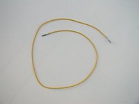
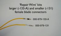
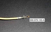
You will need a minimum of 1 'repair wire' from Audi, which can be obtained from your parts department. They are a length of wire with a connector (the same one) on each end. There are various connectors, for this project you will need part number 000-979-133-A, a female blade connector. You cut the wire in half to give you one connector/lead for each headlamp plug that you'll be upgrading (left & right), then you can trim the wire down later.
Repair wire:
Comparison of two sizes of the repair wires, with part numbers. The larger one (-133-A) is what's used for this project.
You will need some common tools, and a wire strip/crimp tool (don't try to substitute pliers). In addition to a roll of electrical tape, you should also have a can of StarBrite Liquid Electrical Tape (I got it at Home Depot). For the actual connections you will need a roll of 18 gauge wire (black is good for these runs), some 18-22 gauge crimp-on butt splices, and some 18-22 gauge tap splices:

Procedure:
First you have to remove the sidemarker lights from the bumper. The left side is easy - just open the hood, reach down below the headlamp to the back side of the sidemarker, and release the clip to pop it out from the bumper. The right side is not so easy. You have to carefully pop out the black plastic grill around the right foglamp, and reach up to the back side of the right sidemarker from below. To remove the foglamp grill (not shown here), there are two clips (top and bottom) on the end fartherest from the foglamp that you can release with a flat screwdriver.
We'll start with the right side. When you have the light popped out of the bumper, you will find two wires going to it. The brown one is the ground - leave it alone. The other one is the + lead. Pull it out of the split plastic conduit, and use one of the tap splices to connect your new wire to it. Always leave a little extra coil of your new wire tied up in case you have to redo something later:

Then, coat and seal the splice with the liquid electrical 'tape', and wrap it tightly with regular electrical tape. If done right, it will form a completely waterproof connection. Zip-tie this tightly to the original conduit:
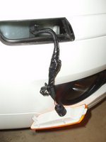
Run the wire in along the existing harness, zip-tying it as you go. Reaching in through the light opening for that fartherest one requres skinny hands and long-nose pliers:
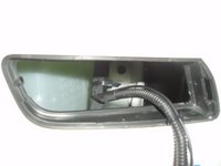
On the right side, there is a rigid plastic cable chase that part of the wiring harness runs through, underneath the neck of the washer-fluid tank. There are two snap clips holding it closed. I managed to get them open and run the wire through the cable chase, then snap it closed again. This keeps it out of the way, completely hidden and protected, and looks 'original'. Getting the snaps open and the wire in there required a heavy wire with a hook bent in the end (made from a clotheshanger):

Now we have the wire up to the headlamp plug, and are ready to attach it. Let's do the left-hand side first, though:
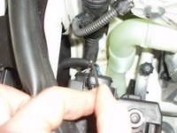
The left light is a lot easier to do. Pop the light out as described above. If you pull the socket out of the lens, you can just pull the harness up where you can reach it from the top by the headlamp. As with the right one, leave the brown (ground) wire alone, attach your new wire with the tap splice, and seal with with the liquid/regular tape as described (photo shows the splice before being sealed & zip-tied).
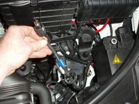
The left side only takes a short run of wire, zip-tied to the existing wiring harness, to reach the headlamp plug. Now we're going to install the new female connector into the headlamp plug.
Remove the plug from the headlamp assembly. There's a little cap around the back side of the plug, release two clips and take it off (not shown here). Locate position 10 - it should have a rubber plug in it with no wire present. Use a small nail in a pair of locking pliers to pluck the rubber plug out:

Using the same nail, pierce the rubber plug lengthwise. It's already partially started, so you'll be able to see what to do:

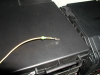
Pass the new repair wire through the hole in the rubber plug, making sure it's in the orientation shown here:
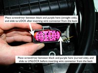
Now you have to get the new female connector into the headlamp plug. You first have to 'unlock' the plug. If you look closely at the purple part of the plug, you'll see an arrow molded into it showing the 'lock' direction. Stick a flat screwdriver between the purple part and the surrounding black part on the CURVED side of the plug, and slide the purple part (it moves less than 0.5mm) until it clicks.
Then you can insert the new female connector into position 10 from the back side of the plug, until it clicks in firmly. It only fits in one way - you can figure it out. If you can't get it all the way in until it clicks, make sure you unlocked the purple part as described above. When finished, tt should look from the front just like the others in the plug, and you should seat the rubber plug into the hole behind it so that it looks like the other wires (make sure you slide the purple part the other way to 'lock' it again):
Use a butt-splice to join the wire you ran from the light to the end of the repair wire you just installed in the plug. You'll need to do some trimming, and the splice should look like this:

Again, seal the splice. Don't use too much tape, so you can squeeze it into the split plastic conduit, then zip-tie it securely together. Snap the cap back around the back of the plug (shown here completely together and ready to plug in):

Replace the plug in the headlamp. (If it won't fit in, did you 'lock' the purple part as described above after installing the connector?) Reassemble and replace the sidemarker light into the bumper.
Repeat the process for wiring the plug on the right headlamp.
Test, and you should have....

...working city lights!
If you do this mod, please email me and let me know how it goes. Photos of your wiring steps are appreciated - I'm curious how other people replicate this process.
No comments:
Post a Comment