Audi DIY, Audi A3, Audi 100, Audi Convertible, AudiCoupe, Audi RS6, Audi S2, Audi A4, Audi S4, Audi A6, Audi S6, Audi A8, Audi TT, Audi Q7, Audi Allroad

Audi A4 (B5). Heater Core Swap

You'll know it's time to change your heater core when your heat starts smelling like coolant, and the interior windows fog up and even the AC won't prevent it. The good news is, there are only 2 screws that hold the heater core into the HVAC box!! The bad news is, it's going to take you about 4 hours to get to those 2 screws.

This writeup is how I did this job, it's not intended to be an exact step by step how to. This job is not for the faint of heart, or small of toolbox.

  • The first step is to take your car to a shop, to have them purge the AC refrigerant. This is REQUIRED, as you have to open the lines into the AC condensor to make this change.
  • Next, move your car to where you are going to be working on it. You will need access to all 4 doors, with plenty of room on either side of the car for parts storage. Try to have the front wheels point streight ahead.
  • Slide the power seats all the way back, and down.
  • Disconnect the battery.
  • Loosen the spring clamps on the heater core hoses, and slide the hoses off of the heater core lines (DO NOT do this with the coolant hot. Let the car sit and cool off fully before starting.):


  • Remove the cover for the pollen filter, and loosen the allen bolt that secures the AC refrigerant lines. Even though you had the refrigerant purged, it may still hiss a little. (at least mine did).


  • Empty the glove box, center armrest bin, back seat area, etc.
  • Remove the driver's side knee guard. There are 2 8mm bolts in the fuse panel area, one behind each of the snap in covers, and one down below.


  • Remove the glove box. With the glove box open, squeeze the sides inward, so they clear the stops. Let it drop down to the floor. Remove the 4 bolts that hold it in. 2 are easy, and obvious, they are on the outside edge, you'll see them when you get the cover off the end of the dash.. The 3rd and 4th one are not.
  • The 3rd bolt is near the plunger switch for the glovebox light.


  • #4 is entirely harder to find.. If you could stick your head into the glovebox cavity, you'd be able to see it. (in this pic, the bolt head still has the electrical tape on it that I used to keep the bolt firmly stuck into my 8mm socket.)


    Now, on to the center console. On the B5, to remove the center console, you start in the back seats.
  • Pull the ash tray out. There are 2 13mm nuts, remove those. You do NOT need to remove the one 13mm lock nut, that one holds the hand brake frame.
  • Under the armrest, there is that little port for the build in phone, pop that out, and look under it. There is another 13mm nut to remove.
  • Pop the trim covers off using a very small, clean screwdriver. Remove the 8mm bolts from each side.
  • Under the hand brake handle is a very small locking tab. You'll need your smal screwdriver again.. just carefully pry it down. What this does is lock the handle to the trim and the lever. Pull the handle and trim off of the lever.


  • With the handle up as far as you can get it, you should be able to slide the rear part of the center console out over the hand brake handle.
  • Next, remove your shifter knob.
  • Remove Radio head unit. Make sure you have your code handy.
  • Unbolt the center stack trim plate.
  • Unbolt the center stack trim from the carrier unit, which houses the HVAC head, the dash switches etc.
  • On the driver's side of the center stack, down by the driver's foot, there is a cover for a nut, remove the nut. You might have removed it earlier, when you dropped the knee bolster.

    On to the dash
  • Remove the 2 8mm bolts on each end.
  • On the passenger side, remove the airbag module and the 3 brackets you will see under the airbag. One bracket is the one the aribag module attaches to, the other 2 are the L brackets, they hold the air bag to the dash frame.
  • remove the 8mm bolts on either side of the center stack, they attach the bracket to the frame behind the center stack. Under the center vent area, that same bracket is attached to the dash cover by 3 8mm bolts.
  • On the driver's side, remove the steering wheel, steering column trim.
  • remove the upper cover for the instrument cluster screws. remove the lower trim for the column pass through. The top screws are accessed from the front, stick your torx driver through the hole along side the column.
  • Remove the instrument cluster.
  • Under the steering column, there are 4 allen head bolts, which hold the column up to the aluminum dash support. Careful here, the column will be free to fall on your head at this point. You can carefully set the steering column on the floor, after you have removed the vacuum line for the cruise control from the brake pedal.
  • While you are at the brake pedal, remove the allen bolt that holds the top of the hinge to the dash support. (I've not done this on a 5 speed car, but I suspect that the clutch will have a similar setup). The pedals will stay where they are, but you need to free the top of the assys. from the dash frame.

    Time to move the center stack stuff.
  • You've unbolted the center stack and removed the trim already. Now, you need to take the electronics, and pull them out, and move the whole deal off to the side.
  • If you look in at the HVAC box, under the area where the center dash vents are, you'll see a duct running from the HVAC up to the dash. There is a single 8mm nut holding this duct to the HVAC box, and a small harness connector.
  • On top of the dash, there is the sunlight sensor. The trim pice comes right off of it, it's a small piece. There is a phillips screw that holds this sensor to the center vent. Remove the screw, lift the sensor up, and unplug the harness connector. (Once you get the dash off, tape a long zip tie to the connector, it will help you fish it through when you put the dash back together.)

    Give it a try..
  • Try to pull the dash cover forward and up. The only thing that holds the windshield side of the dash down are 2 clips. The dash SHOULD come right out now, and you should now be seeing the aluminum frame, the HVAC box, and a ridiculous amount of wiring.


    Legend:
    2. The airbag bracketes. The airbag sits on these, the dash will not come out with the bag bolted to these.
    3. This is where the dash skin bolts to the frame. Not pictured is the center piece, at spot 3a.
    4. The airbag module for the seats. Unbolt it from it's perch.
    5. Remove these brackets. They hold the HVAC box in place in the center of the car. It's held in place on the far right side by the aluminum bracket. It's difficult to see in the below image, but behind the far impact absorber (in the red circle), there is a 3 angle bracket, which is held on by that impact absorber, and also bolts to the aluminum cross member, and the HVAC box.. Remove this bracket.


  • Since you are already on the passenger side, remove the 16mm nut which holds the dash support to the frame of the car.
  • Back on the driver's side, remove the nuts that hold the realy panel etc. to the aluminum. frame. also, there are 2 phillips screws that hold the rest of the electrical bits to the long thin aluminum. arms, way under, by the firewall. On my car, they were broken somehow. it's a good idea to check first, before you yank the aluminum dash support out.
  • Also, remove the 2 bolts, and pop the fuse panel out of the dash support.


  • Remove the 2 16mm nuts on the driver's side, and try to slide the dash support forward. If I haven't forgotten anything here, it should be free to slide forward a bit.
  • The upper dash vent is mounted to the aluminum frame, so you'll want to keep that in mind when you start yanking on the frame.
  • Now you will realize that someone was VERY worried about this huge wiring harness running away, and saw fit to tie it to the aluminum frame every 6 inches or so. Have fun un-doing all of the cable ties. There seem to be 150 of them. Make a mental (or physical) note of it's orinetation around the steering column. This will come in handy when it comes time to put things back together.
  • Once you get the dash support frame free from the wiring, you can take it out of the car completely.

    On to the HVAC box!!
  • With the aluminum dash frame out of the way, you can begin to get the HAVC box moved from it's spot.
  • If you have not already, remove the 2 ducts that route air to the rear seat footwells. These just slip out of place.
  • Remove all of the connectors in sight. Start to pull the HVAC box into the passenger side footwell. Careful to not pull any wores too tight. Basically you want to move it far enough that you can get the heater core out.


  • CAREFULLY remove the old core by unscrewing it, and opening the tabs, then lifting it up and out.
  • Take this time to clean all of the coolant out of the heater box. I've got big hands, and big arms, and I could reach right in with paper towells to clean the stuff out.


  • CAREFULLY clean the new heater core, to get any dust and gunk out of the fins.
  • CAREFULLY install the new heater core.

    Now, start putting things back together.
  • Make sure that the drain for the AC condensor sits nice and tight to the hole in the floor. (that's the strange foam disc at the bottom of the box, right above the top of the passenger side floormat)
  • Make sure you re-connect all of the plugs you disconnected.

    Reinstallation is literally the reverse of this proceedure, plus or minus. I'd really consider this more of a helpful hint article than a full blown how to, but I hope it helps you in some way, even if that is to dissuade you from destroying your car. I'd HIGHLY reccomend having the Bentley manual at the very least before attempting to change your own heater core.
  • Audi A4 (B5). R&R’ing your Power Steering rack

    Special Tools necessary other than a typical Metric Mechanic’s tool set:

    -10mm 12point socket
    -18mm open-end wrench
    -19mm open-end wrench
    -19mm Universal Joint Socket
    -22mm Universal Joint Socket
    -2 ft of 3/8" extensions (can be made w/ several extensions obviously)


    Here is a picture of the 3 important tools needed to remove the p/s rack from the car. It CAN be removed w/o the universal sockets, but it’s a LOT easier with them so spend the $20 for the sockets and pick ‘em up. The ones I used I borrowed from my mechanic. They’re snap-on. I found the 19mm at sears, but not the 22mm, so snap-on might be the only other source.

    1) Get the front end off the ground and remove both front tires:


    I put the whole car up on jack stands, but I was tackling a few other projects after I got the p/s rack removed.

    2) Remove all p/s fluid from the reservoir. You can do this by using a turkey baster discard the fluid, you will need to replace it with fresh stuff.

    3) Remove the lower driver’s side knee bolster and remove the steering column from the p/s rack:


    When removing the steering column bolt, you are going to see a Torx side and a 16mm nut. Do not worry about the torx side. The bolt itself is oblong, so all you need to do is take off the nut and the bolt will slide out. Turn the wheel as necessary to allow you to access the nut. Once it is removed, make sure the wheel is straight again.

    Once the bolt is removed, slide the column up and wire it so the steering column does not separate into two (there is a hole in the column for this very purpose):


    4) Next step is to remove the tie-rod ends from the hub assembly:


    You can get the tie rod out by either using a pickle fork on an air hammer, or I used a 10mm deep socket and used it as a pusher and hammered the tie-rod out. Just be careful not to damage the top at all. As you can see, I soaked it pretty good w/ PB Blaster before I removed anything.

    5) With the tie-rods separated on both sides, you can now removed the access panels that go around the p/s rack ends. There is a 10mm nut holding it in and a few plastic push tabs. Once the nut is off, you just need to pull until it comes off kinda unnerving, but you do whatcha gotta. Make sure you pull near where the plugs are so that there is a bit of support:


    (pic of driver’s side)

    6) Next remove the mounting bolts to the rack. There are 3, and this is where you use the 12 point 10mm socket. One bolt is on the driver’s side near the brake booster, one is under the battery, and the 3rd is under the car on the driver’s side and REALLY hard to see in the pic I provided, but it gives you a general idea where it is.


    This is where the bolt is located (removed in this picture)

    7) Using the universal sockets to remove the banjo bolts from the rack itself. I needed an extra pair of hands to make sure the socket lines up. Also, make sure you have a basin or something to catch the extra fluid from the p/s rack that drains on you. =)

    I found that if you pull the rack towards the front of the car it allows you more access to the banjo bolts. I talked to my mechanic about it, and this is similar to what one of his friends does somehow he manages to get at all the bolts without moving the rack.

    8) Time to remove the rack from the car. It is def easier said than done, but with the help of a friend, feed the rack out the driver’s side of the car. You have to kinda twist it as you pull it out, and move the steering/rotor hub assembly to get it out of the way.

    Here’s a pick of it going back in so you have an idea how you need to twist it. Might also want to put some painters tape on the lip of your fender for those ‘just in case’ instances where you twist the wrong way and whack the rack against the paint.


    Here’s the rack out of the car:


    9) With the old rack out, you need to swap the tie-rod ends from the old rack to the new rack as well as the dampener (if you have one on your car). As you can see, I had one so I swapped it over.

    10) Next comes the fun of reinstalling. You need to feed the rack in slowly and kinda twist it until it snaps in. The Bentley said to use the centering tool (a bolt w/ a chamfered end) but after talking with my mechanic he told me not to bother and I didn’t really need it. He was correct. I guess it just keeps the rack from going off center while you’re installing it so as long as you’re careful it’s really not needed.

    11) Reinstall the banjo bolts. Make sure you replace the crush washers so that you have no leaks. It’s NOT easy trying to get the banjo bolts back in without dropping the crush washers a few times. I had a hard time, and had to contort my hand something fierce in order to get in there and get it threaded. Once you get it started, get the ratchet on the banjo bolts and tighten them down. Get them good and tight don’t have any torque specs, I just really torqued them down =) Redneck engineering style. I haven’t had any issues w/ leaking, so it def did the trick. You can move the rack back and forth as necessary to make it easier to access the banjo bolts from underneath. This is where it was real handy to have a friend helping you, because I could get things started and situated, and he used the ratchet w/ crazy extensions from under the car.

    12) Reinstallation of everything else. At this point, it’s ready for you to start reassembling things. Put the mounting bolts back in the rack and torque them down good and tight. Again, not sure of torque specs, so you might want to look them up. I made ‘em good and tight. Then reinstall your steering wheel column to the rack. Tighten down the bolt/nut combo.

    13) At this point, it’s time to top off your p/s fluid and start priming the system. I filled the reservoir and turned the wheel back and forth about ohhhhh 50 some times? Lock to lock, with the front end still in the air and the engine OFF. Keep topping off the reservoir as necessary. I kept doing this so that I got as much air out of the system as I absolutely could. It worked out really well, because when I did start the car there was NO p/s whine what so ever, so that is proof that the system was properly bled.

    14) Finish reassembling the inside of the car (knee bolster, etc).

    15) At this point, it’s time to fire up the engine and look for leaks. Turn the wheel back and forth and take a look at your banjo bolts for leaks. If they’re seeping, torque down on them a little more.

    16) Put the wheels back on and take the car off the jack stands you are done

    17) Congratulations, you have successfully finished your p/s rack R&R. Sit back, and enjoy the victory. Have a beer, a stiff drink, or whatever tickles your fancy.

    18) Schedule yourself an alignment, because it’s going to be messed up I promise you.

    Audi A4 (B5). Replacing the Engine Coolant Sensor

    Parts: Replacement Engine Coolant Temperature (ECT) Sensor with O-ring gasket; part numbers are detailed below, according to your application.

    Tools: Large Pliers, coat hanger wire

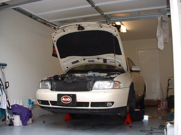
    Estimated Time of Install: 30 - 60 minutes

    Difficulty Level (on a scale from 1-10, 1 being easy as cake): 2.0

    If your dash temperature gauge behaves erratically your car may be a candidate for this procedure. My temperature gauge was varying between the normal (center) position and almost the minimum position during normal highway driving.

    The procedure to change out the ECT is considerably more difficult in a 2.8L engine than a 1.8L due mainly to obstruction. The procedure is the same as Eric Seto as written up in a previous article with minor changes.

    Caution: Make sure engine is completely cold. Unscrew the cover from the engine coolant expansion bottle to confirm there is no pressure built up. Then screw it back on. Screwing it back on will help keep loss of coolant to a minimum when you remove the ECT.

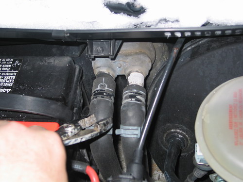
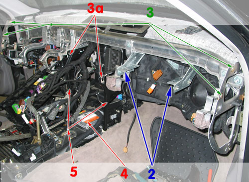
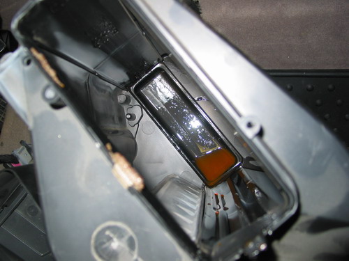
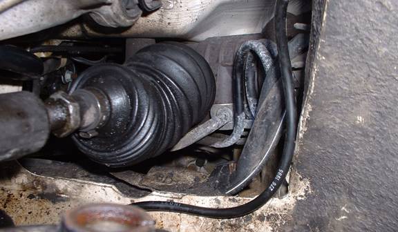
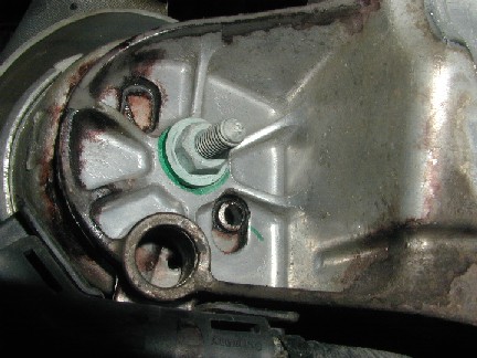
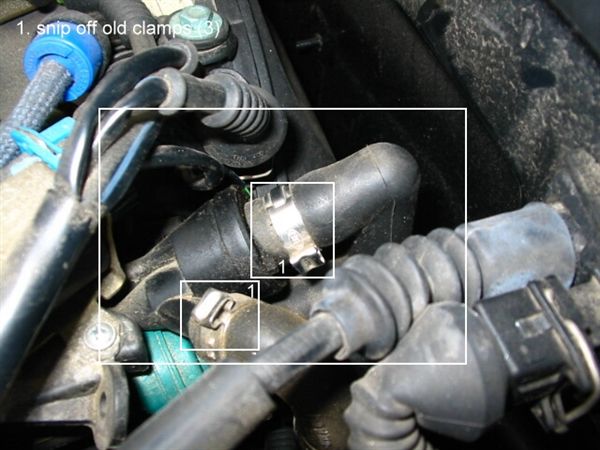
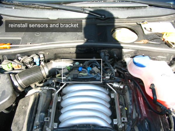
    This picture shows the location of the ECT. Without moving any parts it can't be reached with your hands.


    Picture 1

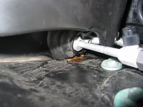
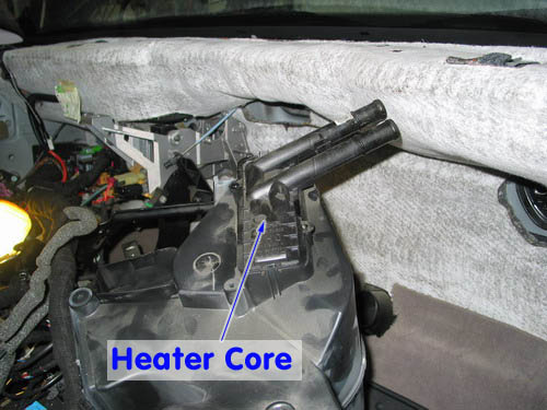
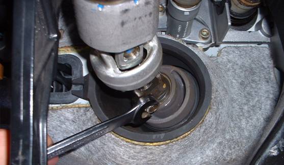
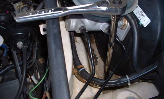
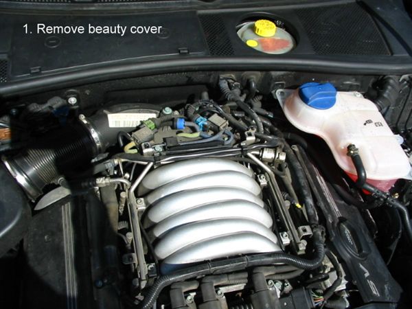
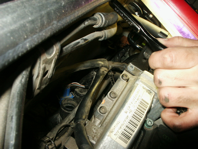
    To make it somewhat accessible begin by removing the plastic and rubber air intake tube that goes from the air box to the intake manifold. Part of the tube can be seen in the upper right corner of the Picture 1. This tube is secured on each end by large clamps. Once the tube is removed you should have access to the one side of the ECT using your left hand as shown in picture 2.
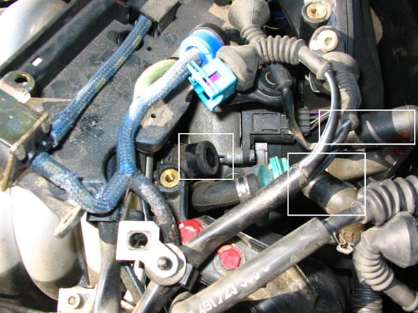

    Picture 2

    Picture 2 also shows a "tool" you will need to make out of a coat hanger. This will be used to hook onto the right side of the ECT connector and unplug it from the ECT.

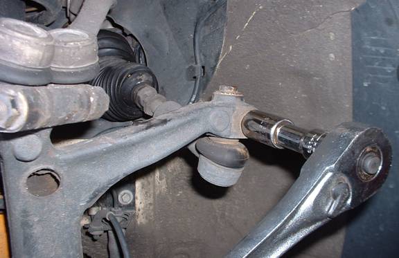
    Leave the wire clip on the ECT connector. It is a lot of trouble to remove and it is not needed to be removed. To remove the ECT connector use you left hand and press the left side (as looking into engine) of the wire clip, then using the "tool" shown in Picture 2 hook onto the right side of the wire clip and pull up and to the left. Be careful don't force it.

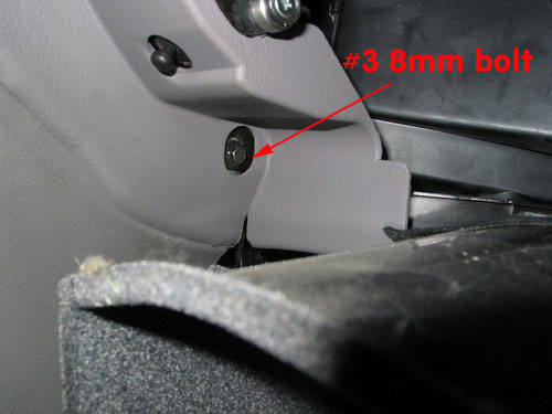
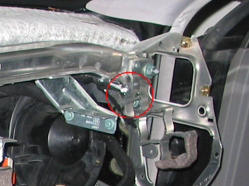
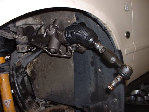
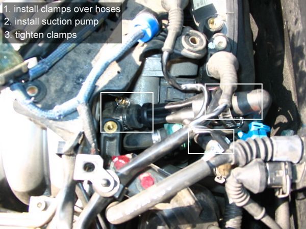
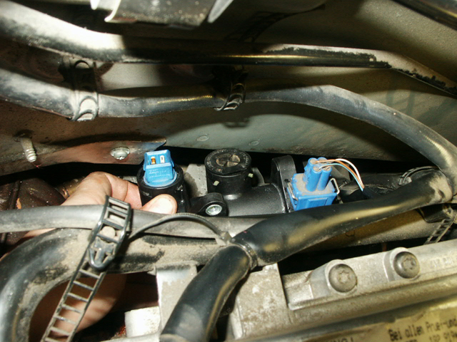
    The result is shown in Picture 3:


    Picture 3

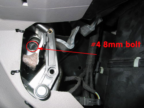
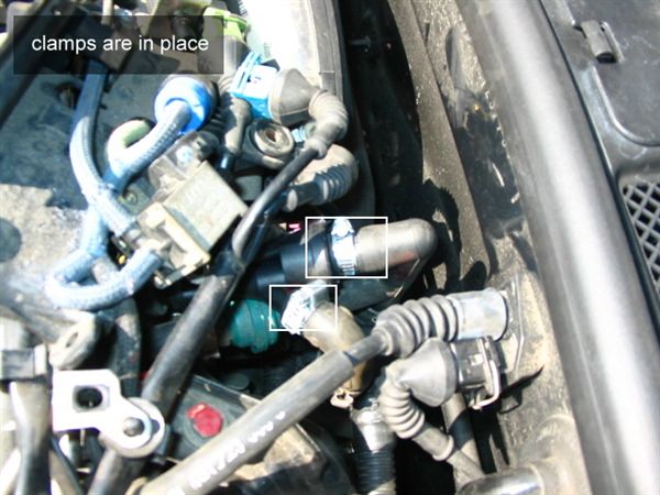
    Now that the connector is disconnected from the ECT you will need to remove the ECT retention clip. Using your left hand reach around all the tubes and pull out the retention clip. Here is the clip removed from the ECT (Picture 4).


    Picture 4

    The trick I used to be able to get at the ECT without removing more parts is I used a large pair of pliers to reach down from the top and carefully grabbed the ECT and pulled straight out.

    After you have removed the old ECT clean the area around it and get a new ECT, clip and o-ring from the Audi dealer.

    My car had a metal ECT retention clip so I chose to reuse that one rather than use the new plastic one provide by the dealer.

    Take the new o-ring and push into the orifice that you just removed the old ECT from. Holding the new ECT reach around with your left and push the ECT into the orifice. When it has bottomed out, using your left hand push the retention clip in from the left side. From the top place the connector in the general area of the ECT and using your left hand push the connector into the ECT until the wire locking clip on the connector snaps into place. Reinstall the air intake tube using the two large clamps and your done. Run the engine and look for leaks.


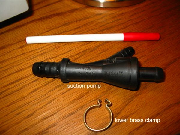
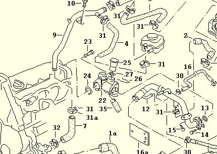
    Picture 5 - For reference

    Blue type ECT: 078-919-501B
    Retention Clip: 032-121-142O-ring: N-903-168-02


    Picture 6 - For reference

    Green type ECT (replacement for black ECT): 059-919-501A

    My car, a 1998 A4 Quattro, 2.8L used the blue ECT, I have provided a picture of the Green type so you can see what type you have.

    Disclaimer: This tech article is created for the purpose of benefiting Audi owners everywhere. I take no responsibility in any damage that may incur while attempting the steps in this tech article. As simple as this process is, please do it at your own risk. Good luck.

    Audi A4 (B5). B5 A4 Engine Mount Replacement

    Couldn't find any good instructions, even tho several have done it. My digicam ran outta juice after one pic, sorry. (WJM-I got your back Steve)

    Passenger Side Mount Removal/Installation:

    FROM ABOVE:

    1) Remove airbox (no other way I could get to the top nut on that motor mount) Stage 3 cars have the turbo VERY close to the mount, a K03 or K04 may have more working room.

    Instead of accessing the nut from the top, I accessed it from under the car. This may not work for everybody but for me it was much easier, and did not have to touch the filter box or the heat shield.

    I first used the regular size 3/8 drive to move the nut, then 1 /4 very small ratchet to undo it completely. Reverse for installation. (
    Comment by Jan Jonak)

    2) Pull heat shield under the turbo up as far as you can to give you maximal working room.

    3) Remove nut...its 13mm...you can only get a stubby wrench on it, and its too tight for that, so use a 13mm 1/4 drive socket that has a hole big enough for the bolt to come through. You won't be able to lock the socket wrench in, but you can get it in just enough to loosen it. It will come off with your fingers after that. (WJM Notes: I was able to break it free pretty easily, and then found I could get a fairly flat 1/4" driver on the nut. I had to finish the removal with the stub wrench though because as the nut backed off the 1/4" driver got pinned against the cat/heatshielding)


    FROM BELOW:

    4) Remove the four 13mm bolts holding the sway bar bushings to the lower frame mounts. You may need to loosen the end links (I did, WJM-So did I) and just swing the bar out of the way. 16(18)mm bolts on the end links.

    5) I removed the turbo to hardpipe hose to get more working room, but it may not be necessary, YMMV (WJM-You don't need to do this at all).

    6) Mark the spot where the bottom mount nut is relative to the bracket. Just draw a circle around it with a marker. Also notice where the little nub protrudes from the mount into the hole on the bracket. Look at your new mount...see how it has one nub, but the bracket has holes 180 degrees apart? This lines up the top of the mount, so mark it.


    7) Remove the lower nut from the engine mount.

    8) Rig up a way to hold the engine up. I used a hydraulic jack, a piece of 2x4, and a piece of 3/4" plywood to push on both the oil pan and the snub mount bracket. Don't raise the engine, or raise it just a hair so you know you have it. Make sure this is stable. I put a jackstand next to it for safety (engine's...not mine).


    9) Remove the three 18mm (who the f' uses 18mm bolts...f'n Audi...had to run to the store for that) bolts holding the mount bracket to the frame. Two forward bolts aren't too bad, but you may have to invoke the name of your favorite supreme being to get the rearward bolt loose. (WJM-Breaker bar makes it easy...no problems here)

    10) There is some wiring attached to the bracket, it will keep it from falling out, but it can be rotated to allow the engine mount to come out. Pull it out and grab the washer that is on top of the mount. Put it on the new mount. Slide the new mount up and into place, remembering the little nub on the bottom, and making sure the two tabs go into the slots on the top bracket. (WJM-Its hard to see, but if you look at your new mount you will see two tabs or ears on the top. These locate the mount into the bracket. When you install the new mount, you will feel it "seat" in the proper orientation, just take note of the nub side....again I think there are openings 180 deg apart so it probably doesn't matter, but might as well)

    11) Push the whole assembly back into place.

    12) Bolt everything back together...one caveat...it will be very hard to get the top nut tight. I got it flush by hand, then used a stubby 13mm wrench and got it fairly tight. Then I put the 13mm stubby wrench on it and used a 3/4 long wrench to push the stubby 13mm wrench. (WJM-Remember that 1/4 " ratchet? Yeah will it fit again and I was able to snug it down real easily J )

    ***NOTE: If doing driverside mount, fully install the passenger side mount, but do not reattach the sway bar.***

    Driverside Mount Removal/Installation:

    The driverside is very similar, yet easier than the passenger. Since the sway bar is disconnected all you have to do, is:

    13) Remove the three screws that hold the coolant reservoir tank in position, disconnect the sensor wire, and swing the reservoir out of the way.

    14) With a 13mm socket, remove the top engine mount nut.

    15) It *looks* like you need to remove the cross over tube-to-intercooler hose, in order to remove the bracket, but you do not.

    16) Conduct steps 6-12 from above...

    17) Reattach sway bar, and retighten end links.

    Be careful, work slow, you should have no trouble.

    Thanks to Chad (180q) for recommending dropping the lower bracket and swaybar.

    Took me about an hour total...i work slow, don't have a compressor or an impact gun :) (WJM-Took me 2hrs to do both Driver and Passenger side mounts, I'd plan for 2hrs if you are doing this with hand tools, that top nut can make or break you)

    Audi A4 (B5). Suction Pump Replacement

    Not a difficult job, but it is a pain in the *ss working in the rear of the engine bay.

    This job took me roughly 20-25 minutes, mainly because I tried to get it done without really moving the sensor bracket covering the pump. Stupid. The single use clamps used on the pump/hoses are a PITA, because you have to cut them off and remove them; I have some nice little finger cuts from the sharp edges.

    At the end of the process, I'm thinking that it was a useless swap for me because I could blow through either pump just as easily. So now what? How do we know when these things get clogged? Should this become a task that's performed with every oil change? I have two working pumps, so I could just keep swapping them out.

    I'm a little worried about the lower clamp. The lower clamp was the only brass clamp and I replaced it with a standard hose clamp. I'm not sure if the extra strength of the brass clamp is necessary. Otherwise, it's business as usual.


    Anyhow, here's the replacement process:

    The tools and items you'll need:
    suction pump, part number "058 133 753 B"
    3 #6 hose clamps
    a 10mm socket
    socket wrench
    phillips screwdriver
    flat head screwdriver

    Step 1, remove the beauty cover


    Step 2, swing sensor bracket out of the way. 3 10mm bolts, 2 phillips head screws, one sensor clip.


    Step 3, remove single-use clamps (I used a tin snip to cut them away)


    Step 4, remove hoses from suction pump


    Step 5, place replacement clamps over hoses, install hoses onto new suction pump.


    Step 6, tighten clamps


    Step 7, reinstall sensors and sensor bracket


    Step 8, reinstall beauty cover. Done.

    Audi A4 (B5). Coolant Flange Replacement

    If you have been losing coolant, or had a coolant burning smell after a long drive, or just happened to look down towards the back of the engine in between the firewall and noticed some pink crusting; then it's most likely time for a coolant flange job.


    Picture by Andy TN showing some pink crust


    The coolant flange holds the ECT (Engine Coolant Temperature Sensor) and is connect to the back of the engine head. It's a simple but semi hard to reach job but it's definitely DIY.

    Let's get started:


    Old vs. new. This side is the R side that will connect to the big black coolant pipe. Make sure you have a gasket in there


    Coolant flange is semi installed. It's hanging in there loose


    This side shown is the side that will attach to the engine, make sure that the gasket is installed and not torn... this is a leak area


    The new flange with the temp sensor installed but no gasket between flange and engine


    ETKA explosion diagram of the coolant flange and its connections


    Some of the old coolant flanges will only have ONE port. The new ones that are sold come with a second port, that is seen PLUGGED in this picture. Make sure you have either an old temp sensor or the dummy plug from the dealer to fill the second port.

    OK so now that you know how the coolant flange looks and where it connects to its time to get dirty:

    You will loose some coolant during this procedure; it is also a good idea to replace the ECT as well while you are doing this.
    You could either drain the engine coolant at the water pump or just leave whatever you have in there and see how much comes out.
    I did the replacement on an engine that had all the coolant drained and replaced with brand new G12. Either way, make sure that the Engine is COLD or you will get burned.

    Disconnect the cable leading to the ECT by squeezing the metal and pulling it off. You can leave the ECT in the flange or remove it. To remove it pull the small plastic U shaped clip out towards the firewall and then pull up on the ECT. You will have some coolant coming out right now.

    I can't remember for sure if I had 6mm hex bolts of 8mm ones. But you need to remove 2 bolts that attach the coolant flange to the engine and another 2 that attach the flange on R side (looking from the front) to the black hose.


    The picture to remind you. After you have those bolts loose you will have some more coolant come out. Pull the flange away from the engine block and also out of the black hose. The only connection that is left now will be the bottom hose.

    In order to remove the bottom hose from the flange you will have to pull away a clip from the hose that will be on the flange. Make sure that you try to catch this clip as it will be flying away; it's very small and hard to find. After you have pulled the clip, hold the hose with one hand and pull on the flange with the other hand.
    The flange will pop out with enough force.

    Take your new flange and transfer the dummy plug and or new ECT from the old to new if needed.
    You hopefully have 3 or 4 O-Rings depending on the flange. One O- Ring goes in between the flange and the engine, the other one goes between the flange and the black hose and the 2 other ones are for the ECT and the dummy plug.


    Installation is in the reverse order. Make sure that when you tighten the bolts back up so just barely hand tighten them until everything is connected. Tighten them down a little bit at a time so the flange is not crocked installed.
    Replenish the coolant lost, start the engine and check for leaks.

    When i removed the old flange I didn't see any physical damage to it, so it might just be the O rings that are failing.

    Good luck!

    Audi A4 (B5). OIL COOLER INSTALL

    For those of you that have front mounted intercoolers and that take your car to the track, you've probably already experienced overheating on hot days. Regardless, an oil cooler provides additional protection to modified turbocharged Audi engines. This install was performed on a 1997 Audi A4 1.8T Quattro with an SPP front mount intercooler. Installation on any other vehicle may vary from the following guide.

    No liability is assumed by the author for the use or interpretation of information contained within this article - all decisions based on the information provided herein are the responsibility of the individual user. The user understands that any modifications to the car can void warranty.

    PARTS LIST
    1 ea. 48 Plate Mesa oil cooler, part #3080-11.....................................................$59.99
    1 ea. Mocal sandwich plate, 3/4 x 16 with 180 degree thermostat, part #10.117.304K..99.95
    1 ea. Shorter threaded 3/4 x 16 nipple for oil filter mount, part #1234-3/4 x 16................3.49
    3 ft. XRP push-on hoses, size 10, part #340010.....................................................6.00
    2 ea. Straight push-on hose ends, size 10, part #230010..........................................7.50
    2 ea. 45 Degree push-on hose ends, size 10, part #234510......................................24.00
    4 ea. Male size 10 flare to 1/2" NPT pipe adapter, part #98160.....................................5.35
    4 ea. Snap type hose clamps, part #81840.............................................................1.46
    2 ft. Aluminum L material, part #ALUM 1" X 18" Crown Bolt 1/16" thick
    5 ea. Bolts, Nyloc lock nuts and washers, 6mm x 12mm
    1 ea. Bolt, 6mm x 20 mm bolt
    1 roll Teflon Tape
    2 ea. Sheet metal screws, 7mm x 20 mm (approx.)
    Total (approx.)............................................................................................. 223.67

    SOURCES:
    Porterfield : (porterfield-brakes.com) Hoses, hose ends, hose clamps.
    Pegasus Racing: (pegasusautoracing.com) Shorter threaded nipple for oil filter installation.
    VWParts: (vwparts.net) Mesa oil cooler.
    PUREMotorsports: (pure-motorsports.com) Mocal sandwich plate.
    Home Depot (homedepot.com) Sheet metal screws, Teflon tape, metric nuts and bolts, aluminum L bracket material.

    TOOLS/SUPPLIES LIST:
    Floor jack and jack stands
    Metric sockets: 10mm, 13mm, 14mm, 19mm (12 point), 26mm (or 1")
    Allen sockets: 5mm, 6mm, 8mm
    Breaker bar
    Torx sockets: T45, T30
    Set of metric wrenches
    Fresh G12 Coolant (2-3 bottles if you change the coolant)
    New Audi filter
    5 Quarts of oil
    2 Buckets to catch coolant and windshield washer fluid if you want to reuse those
    Drill
    9/32 drill bit
    Screwdrivers, phillips and standard
    Hammer
    Center punch
    Vice grips or channel locks
    Hack saw
    Dremel with cutting wheel

    Step 1 Disassembly
    Remove front clip. Although removing the bumper, bumper supports, A/C condenser and radiator may be optional; removing it provides additional room to work.
    For a detailed step-by-step procedure on how to review the front clip, follow the first six steps from Andy TN's timing belt replacement on Audiworld's tech articles.

    The only difference is that you'll also be removing your FMIC and a few other parts to improve access.
    Once you've completed step six of Andy's timing belt tech article and everything is out of the way, proceed with the next steps:
    - Drain the oil and remove the oil filter.
    - Remove the coolant overflow tank and electrical connector.
    - Remove driver's side wheel/tire.
    - Remove the driver's side wheel liner.

    Step 2 Remove existing oil cooler
    Remove existing oil cooler and coolant lines.


    Remove the jam nut (8) from the threaded tube (5) that goes through the middle of the oil cooler (7). Then unscrew the threaded tube (5) for oil cooler. Use a vice grips or similar tool to unscrew the threaded tube. You can cut and reuse the original tube if you don't damage it. If you plan to cut it and reuse it, use care to not damage the threads when removing. Wrap threads with a towel or similar item to protect.


    Remove the feed line and return hoses from the oil cooler. Using pliers, squeeze the clamps and slide them up and off the oil cooler. Then pull off both hoses. You will re-use the hose 058 121 058 A that goes from the throttle valve housing to the oil cooler. To be safe, you can purchase a new hose, although mine looked to be in good condition so I just reused it.
    The oil cooler should basically fall off at this point.


    Step 3 Prepare oil cooler for installation
    Trim oil cooler bracket. The oil cooler on the right hand side must be trimmed to fit; otherwise it will contact the washer fluid reservoir. Trim two inches from the right hand support bracket as shown. You'll also need to drill a 6mm hole on the right hand side, measured 4 1/2" from the bottom.


    Wrap the two male flare to pipe adapter fittings with Teflon tape and install them into the oil cooler.


    Step 4 Fabricate brackets for oil cooler
    Three aluminum brackets must be fabricated to support the oil cooler.
    * The first bracket will attach to the left side of the oil cooler to the frame of the car.

    bracket 1 Take the angle aluminum and cut it to 8-1/4" in length, slightly shorter than the inlet and outlet on the Mesa cooler. Align the bracket with the oil cooler and mark the holes. They should be 1-1/2" and 6-7/8" from the top of the angled aluminum. Drill two 9/32" holes for mounting the Mesa cooler to the bracket. Mark the holes on the other side of the angle aluminum that will screw into the frame. Mark the first hole 2" from the top and the other 3" from the top. Now, bolt the angle aluminum to the cooler and test fit it to the car frame just to be sure the holes you are about to drill are centered vertically to the frame. The bracket and cooler should be positioned so that the top of the cooler is just below the top edge of the old SMIC mount. If everything looks good, remove the bracket and drill the two holes for the sheet metal screws that will go into the frame.


    bracket 2 The second bracket will support the cooler from the top. The overall length is 5-1/2". You'll need to make two cuts to leave a 1-1/2" tab at top and a 45-degree angle. Drill a 9/32" hole in the center of the tab for the bolt.
    bracket 3 The third bracket will support the cooler from the back. Cut the aluminum stock 4-7/8", trim 3/4" from each end so that the bracket can have two angled tabs as shown. Drill 1/4" hole in the center of each tab for the bolts.


    Step 5 Install the oil cooler and supports
    Test fit cooler again with all three brackets loosely attached.


    The left-hand bracket should be placed so that the top of the cooler is just below the top edge of the old SMIC mount. Mark the holes from the left side bracket onto the frame. Note where the top and back brackets will be attached. The top bracket will bolt into the old SMIC bracket and the back bracket will bolt into the existing fender mount using a longer bolt in place of the existing bolt.
    Install the side mount bracket. Make sure the holes are centered, then use a drill punch to mark the holes and drill holes in frame.
    Temporarily mount oil cooler. Attach the left-hand bracket to the frame with two sheet metal screws and bolt the oil cooler to the frame. Recheck the fitment of the cooler and the two other brackets. Mark the hole in the SMIC for the top bracket, use center punch and drill hole.


    Loosely bolt in place. Using the longer bolt, attach back bracket. Make sure that the wires that run under the top inlet are clipped in place and won't be damaged by any heat off of the oil cooler. Wrap with thermal wire protection if needed.


    Check that all brackets fit properly, then tighten all the bolts and nuts down.

    Step 6 Install Mocal Cooler
    Install Mocal cooler.


    Install the two short blue fittings into the sandwich adapter using pipe thread tape. At this time also wrap the other end with pipe thread tape so it is ready to accept the oil lines from the cooler. Install brass looking threaded tube into the engine block, then the Mocal cooler adapter and the jam nut. (The other red knob unit is a snub mount that I installed at the same time) Tighten jam nut to 18 ft-lbs. Oil the filter gasket on the new oil filter and spin it on tight, plus a half turn. Install the oil drain plug so we are ready to begin adding oil.

    Step 7 Assemble oil lines
    Double check length. Take the lines and check that they are the correct lengths. They should have some slack and be routed so they won't rub on other existing lines. Once you are satisfied that the line length listed above is correct, cut the lines and install the hose ends.


    Assemble bottom line. Using 17 1/2" line, push the oil line onto one of the straight ends with washer. Then slide both clamps onto the hose and install the 45-degree end with washer. Recheck fit.
    Assemble top line. Using 12 1/2" line, assembly will be same as the bottom line. Recheck fit. Then clamp all the fittings to the lines. Use a vice grips or channel locks to secure the clamps. I wasn't sure exactly where to clamp the lines in relation to the ridges on the hose ends. I tried both positions, one right on the highest point of the ridge and the others in the lowest point. So far, no difference and no leaks.


    Step 8 Install Line Sets
    Install oil lines. The male fittings should already be wrapped with pipe thread tape. Install the bottom line set. The 45-degree fitting goes on the oil cooler and the straight fitting goes to the sandwich plate.


    I didn't torque the fittings, but they are very tight. Install the top line to the cooler only. Holding the line up, prefill the lines and cooler with oil. Once the lines and cooler are full of oil, install the other end of the line to the sandwich adapter.

    Step 9 Reinstallation of all other components
    Install coolant lines. Since the coolant lines will bypass the oil cooler they need to be rerouted. Using the long line, route it from the upper coolant hose to the lower heater core coolant hose. Clamp both ends of the hose. Reuse existing clamps or purchase new screw clamps. (I reused OEM clamps)
    Fill with system with coolant. Be sure to purge the air from the system.


    Step 10 Final Preparation
    Fill engine with oil. New capacity is roughly 5 quarts of oil. Check dipstick as you fill.
    Start the car and check for leaks. Since the oil cooler lines won't be carrying any oil until the thermostat reached 180 degrees (the preset temp for the Mocal thermostat) be sure to recheck the system for leaks the first time the engine oil reaches 180 degrees.
    There you go, nice clean install. Looks nearly stock.