Background on the exhaust flap: in the Golf R32 and TT 3.2, the right tip of the exhaust has a "flap" that opens and closes depending on speed and RPM variation. The intent of the design was to have a quiet exhaust when gently driving around town, to abide by German noise pollution laws, but to also "free it up" and make it loud when driving aggressively.
What is the use of this mod: to have full control of when the exhaust flap is opened or closed! The ECU has a somewhat wacky way of controlling the flap depending of speed and RPM's:
1. Under 7 mph and no matter what RPM, the flap is OPEN
2. Above 7 mph, and:
a) above 3100 RPM (after increasing the rev's to above 3100), flap is OPEN
b) below 2700 RPM (assuming the rev's already went above 3100), flap is CLOSED
Which means that, from idle to 3100 RPM's (assuming the engine hasn't gone above 3100 yet) the flap is closed!
The valve that controls the flap is connected to a solenoid, which gets a signal from the ECU as to when to open and when to close the flap. When the ECU sends a +12V signal, the flap opens up, and when the ECU sends the signal to ground (0V), the flap closes.
To take control of the valve, we can simply re-wire the lead that goes to the solenoid by connecting it to a switch. Unfortunately this cannot be a simple on/off switch if you want to control the full 3 modes of the flap (always open, always closed, or stock), and even if you just want "always open" and "always closed" you have to find a way to ground the solenoid to keep the flap closed, and send it +12V to keep it opened.
In my mod, I chose a slightly different switch that the R32 guys. It is a DPDT (Dual-Post Dual-Throw) 3-way ON-ON-ON switch, which has 3 different combinations of connecting 6 posts.
Beyond the two leads that will come from cutting the control wire in half, we need a +12V lead and a Ground lead to make the valve close the flap. The sample diagram will look something like this:
The intent of the resistor connected to the +12V signal is to connect the ECU side of the control wire to some power source, in order to "fool" the ECU that it is still connected to the solenoid - otherwise it will throw an error code such as follows:
1 Fault Found:
19475 - Valve for Exhaust Flap 1 (N321): Open Circuit
P3019 - 004 - No Signal/Communications - Intermittent
Anyway, the switch connections will be explained further in details later, when it comes to actually connecting it.
But for now, the result of the switch is as follows:
1) In the top position, it will only connect the ECU to the solenoid, so you will be in stock mode (as described above)
2) In the middle position, it will connect the ECU to the resistor, and the solenoid will stay disconnected, so the flap will always stay opened and the exhaust will be LOUD :-)
3) In the bottom position, it will also connect the ECU to the resistor, but this time the solenoid is grounded, so the flap will always stay closed and the exhaust will be QUIET.
*I highly recommend disconnecting the battery as you will be touching live terminals under the dash, so please do yourself a favor and disconnect the battery to avoid headaches later (and keep the trunk open since the battery is in the back!)*
Step 1: Open up the dash
a) After opening the driver-side door, remove the panel which covers the fuse panel with a flat screwdriver, or if you have numbed climber's fingers...

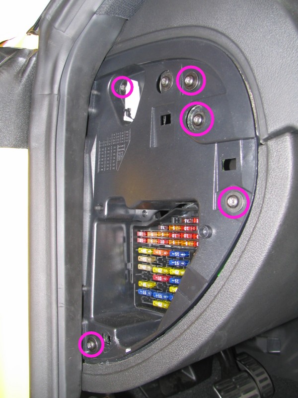
b) Remove these 5 screws shown below using a torx screwdriver:
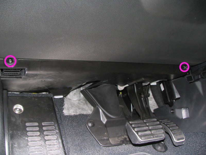
c) Remove the remaining two screws under the lower dash panel:
d) Carefully pull the lower dash panel to remove it while liberating its left side by pushing the fuse panel to the left
e) Unplug the two headlight housing connectors at the top of the panel, and the VAG connector at the bottom of the panel
Now you have access to the relay panels shown below, behind which the wire harness you need to tap into is located:
Step 2: Find the gray w/ blue wire.
Warning: this can be a major PITA.
You have to first remove the relay panels then open up a wire harness (by cutting the tape that covers it), which is way the heck up there, so be ready for some back aches and finger cuts...
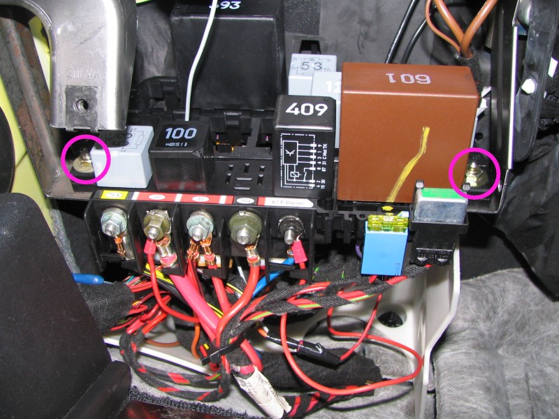
a) Remove the relay panels by unscrewing these two hex nuts:
b) I highly suggest removing the top panel's relays and connectors to completely free up the space required to do the dirty work. Remember which connector & relay goes where! Here are a couple of pics to help you a bit:
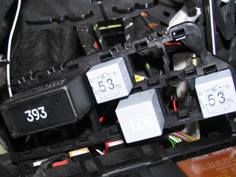
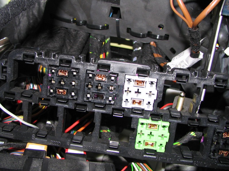
Note that the wide top-left relay uses two connectors that are actually one piece behind the panel (if that makes sense...)
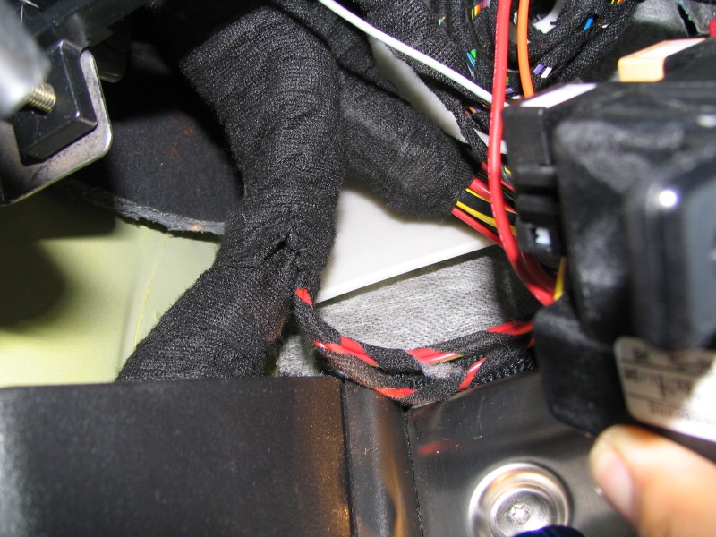
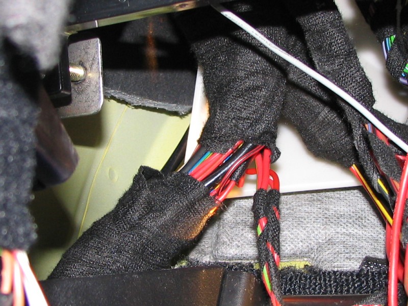
c) Now you can see the wire harness, above and to the left of the aluminum dead pedal. You'll need to start cutting the tape right around the point where the two red wire bundles join the harness:
d) Here's some progress after a few minutes of cutting the tape, but still not enough:
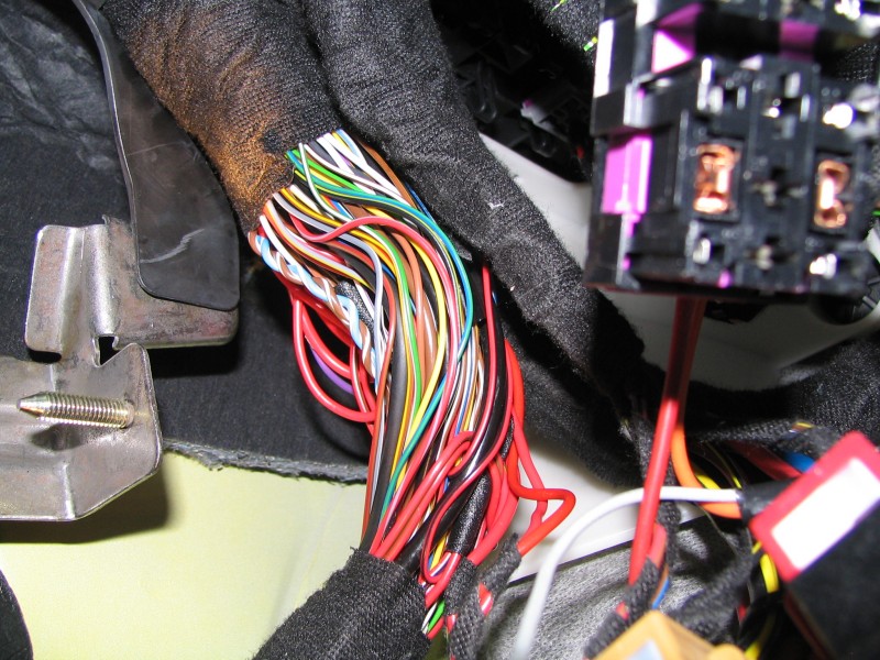
e) Finally after about 4 inches of tape removal, which seemed to be enough, this is what your harness now looks like:
f) Now the major PITA is to find the CORRECT wire, which is a 0.5 mm square (~20 gauge) gray with blue stripe wire. The problem is that there were TWO such wires in my bundle, and I first cut the wrong one... here are the two wires I found:
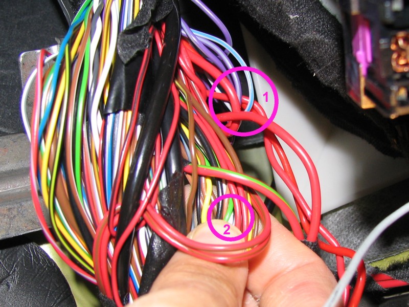
The #1 wire is a little thicker and actually loops back up the harness. This is the one you want to cut.
The #2 wire is a little thinner, but comes from the bottom of the harness to the top so beware not to cut this one.
Step 3: Connect the control wire to your own wire harness
In this step you will have to connect each end of the valve control wire to your own wire harness, which will be run to the console and eventually connect to the switch for maximum flap control =)
a) Cut the wire around the bottom of the loop to have equal lengths to work with, and strip the ends so that you can connect them to wires of your choosing:

b) Pick or create a 4-wire bundle long enough to run from the left side of the dash to the centre console. I already had this 4-wire harness with 3 in-line fuses, which is perfect for our application (always want to keep a live wire fused!)

Connect two of the fuse lines to a standard 2-way crimp connector or other connector of your choosing, and the two other wires (ground and +12V) to ring or U-terminals. In my case I chose the black wire as ground, red wire as +12V, and brown & orange wires to either ends of the control wire (we'll have to determine which one is which later). Make sure to write your colors down!
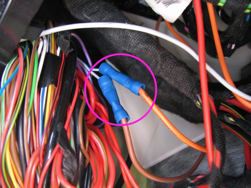
c) Connect the two (brown & orange) wires to the cut control wire and crimp them down together:
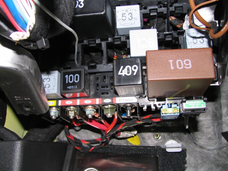
d) Connect the (red) +12V wire to the right-most terminal of the relay panel, which reads "87 F Diesel":

e) Connect the (black) ground wire to the existing star-looking bundle of ground wires:

f) Re-tape the wire harness a bit and push it back where you pulled it out from to work on the wires:

g) Run your new wire bundle behind all the relay panels, the other harnesses, above the pedals and into the rear part of the console shown here:

See the 3 RCA plugs on the right? That's where I eventually placed the switch, but of course you could mount it anywhere you like as long as the wire bundle you run makes it there.
Step 4: Testing the leads for correct voltage
This step serves a dual-purpose: to make sure every wire is connected properly, and to determine which side of the control wire goes to which wire that will be run through to the switch.
a) Verify that you have 0 resistance between the ground (black) wire and the star-shaped "hub"
b) Verify that you have 0 resistance between the +12V (red) wire and the "87 F Diesel" terminal
c) Verify that you have 12 Volts when measuring between the +12V (red) and ground (black) wires - note that the ignition must be turned to ON (engine not necessarily running) to have 12V across these leads
d) Now connect your voltmeter between the ECU or Solenoid (brown or orange) and ground (black), strap it to a visible place on your dashboard and go for a ride! But first...
e) Replace the relays and their connectors in the relay panel (run Step 2-b backwards)
f) Screw the relay panels back where they belong (run Step 2-a backwards)
g) Reinstall the lower dash panel and fuse panel & its cover (run Steps 1-e/d/c/b/a backwards)
h) Reconnect the battery!
i) Ok, now you're on the road, and one of your ECU or Solenoid leads displayed on your voltmeter. If the voltmeter reads 12 Volts or more *constantly* this means you have the Solenoid lead. Otherwise, it will either read around 3.6 Volts (that means the flap should be opened) or close to 0 Volts (flap closed). Note that during your test drive, it will keep the flap always opened since the ECU is not grounding the Solenoid. You will definitely hear the difference when the RPM's are between idle and 3100!! =) Now connect the other ECU or solenoid wire, and confirm that the other voltage behavior is observed. Also note that, since the ECU is no longer connected to the Solenoid, an error code will be thrown by the ECU and the Check Engine light will go on. Not to worry though, it will soon disappear after you connect the switch.
Step 5: Onto the switch setup!
As I mentioned in the beginning (i.e. a while ago...) the switch must be a 3-way DPDT ON-ON-ON toggle switch in order to "safely" have all 3 modes.
Here are four switches I purchased online, as I couldn't find one with the right specs locally: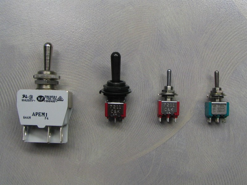
From left to right, we have the following part numbers from the manufacturers:
- APEM 644H/2
- ITT/C&K 7211TZQE22
- ITT/C&K 7211SYZQE
- Electroswitch A232S1YZQ
I ended up picking the black ITT one, since it looks the least conspicuous in the TT's centre console. Also its actuator is a fair bit larger than the other two small ones while having the same small connector size.
Here's a sample diagram of the switch I ended up using: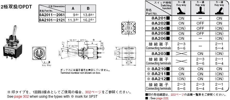
What's most valuable in this diagram is the "connecting terminals" row that shows which of the switch's poles are connected together in every position of the switch's actuator.
Note that it says the P/N for the one we need is "8A210" in this chart, but the complete P/N for the switch is actually 7211SYZQE, which has the same electrical properties as the 7211TZQE22 I ended up using (just different mechanical parts).
Now given the wiring diagram I drew in the first post, and the electrical requirements of this mod, let's assume that:
A = resistor w/ +12V lead
B = wire from ECU
C = solenoid end
D = ground
The intent is to have three possible modes:
A+B = ECU connected to resistor = "loud"
B+C = ECU connected to solenoid = "normal"
C+D / A+B = ECU to resistor, solenoid to ground = "quiet"
Now all that's left is to match a wire to a post (or two), as follows:
A = 3
B = 2
C = 1 and 5
D = 6
Going by the switch diagram above, there are three positions:
Left = 2+3 / 5+6 = B+A / C+D = "quiet mode"
Center = 2+3 / 5+4 = B+A / C+? = "loud mode"
Right = 2+1 / 5+4 = B+C / C+? = "normal mode"
I know this sounds a bit complicated, but matching the switch poles to the correct leads is crucial.
Let's wire up the switch then!
Since the +12V lead needs to first be connected through a resistor before hitting the switch, and to make things cleaner, I decided to use a PC board.
a) Create holes large enough in the PCB for the switch to fit: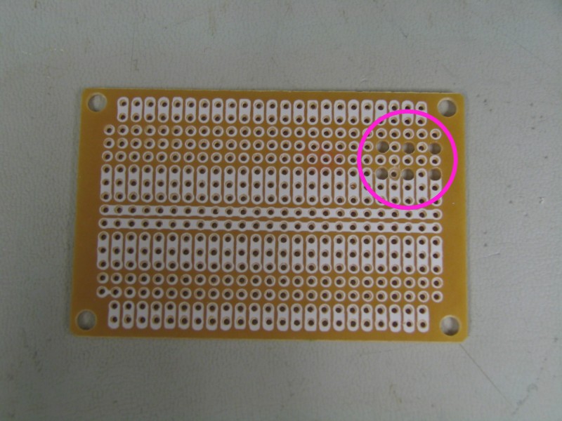
b) Cut the PCB down in size as we won't need the entire surface:
c) Make sure the switch fits snug into the holes: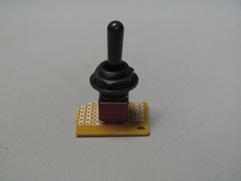
d) The switch leads should stick out the back a bit for soldering purposes:
e) Here's one side of the switch where poles 1, 2, and 3 are connected to C, B and A respectively (where A is the +12V lead first going through the resistor):
f) Here's the other side of the switch with poles 5 and 6, connected to C again (green loop wire) and D respectively: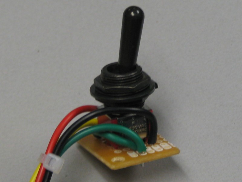
g) Here is the "behind-the-scenes" soldering job: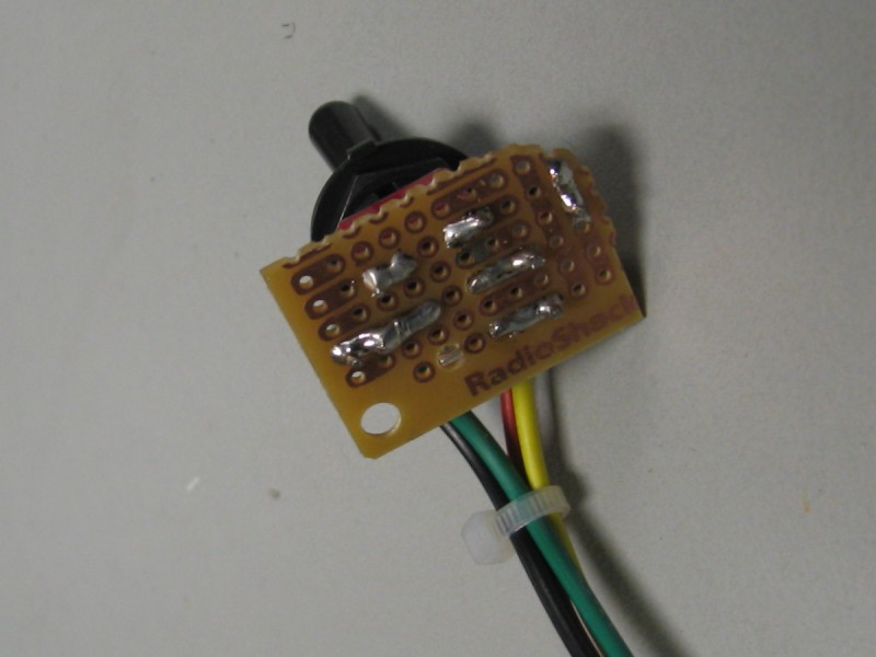
h) I connected the end of these short leads to female connectors, and voil?! the switch is ready for action: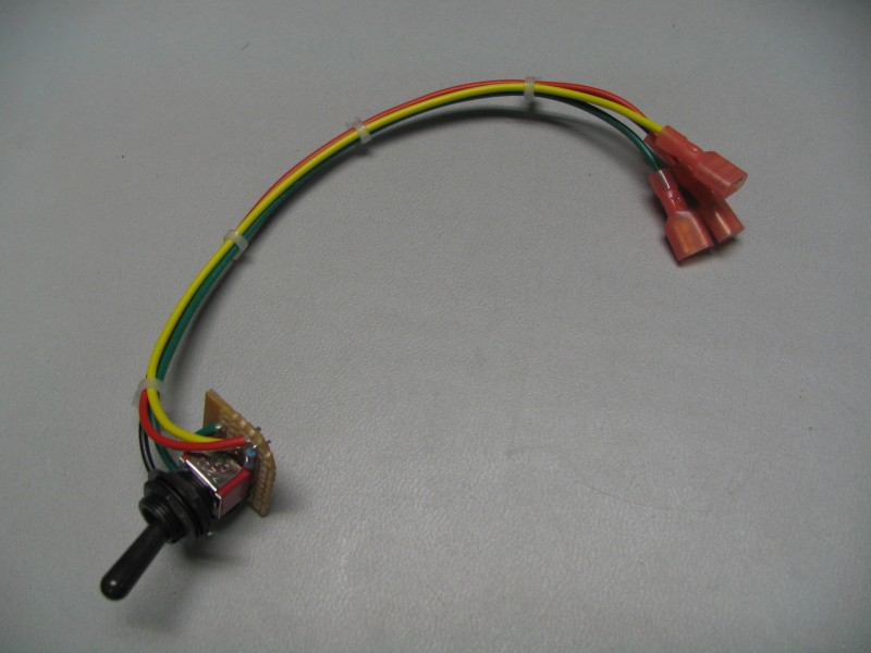
Step 6: Finally, the switch goes in!
Remember the "L-shaped" console piece shown in Step 3-g? That's where I wanted to place the switch, so I felt down to where the switch would be in the best position and marked it, then took the console piece out.
a) Drill a hole where the switch is to go:
b) Pass the switch from behind the trim piece with one nut and a washer, then tighten down the front side with another washer and another nut:
c) Here's the rear side of the switch in its final place:
I do recommend covering the back of the PCB with some hot glue or electrical tape to avoid shorting any leads.
d) On the wire bundle that came out from behind the dash in Step 3-g, connect each lead to a male connector which is the counter-part of the female connector setup in Step 5-h (make sure to remember your color-coding now!) then connect the wires together, keeping in mind which one is which (in my case it was easy, since I made sure to use the same colors on both ends):
e) Reinstall the left L-shaped center console piece:
f) From the right side, this is how it looks like "behind-the-scenes" (the right-side L-shaped trim piece was first removed):
g) Make sure the wires don't interfere with the console cover as it slides into its open position:
h) Replace the right L-shaped trim piece, and Voil? - you are done!!!
i) Here's how the switch looks like looking at it from the hand-brake level (now you see me):
j) and from the driver's eye-level (now you don't!):
Now I notice a big difference in sound between the low RPM ranges mentioned above, especially around 2000 RPM.
The best news about this essentially "free" mod is: you gain about 7 HP and 5 ft-lbs of torque!!
Check out this post from the R32 forum from a guy who did a couple of dyno runs to compare the different switch modes.
Thanks again to all the R32 pioneers who made this happen!!!
No comments:
Post a Comment